
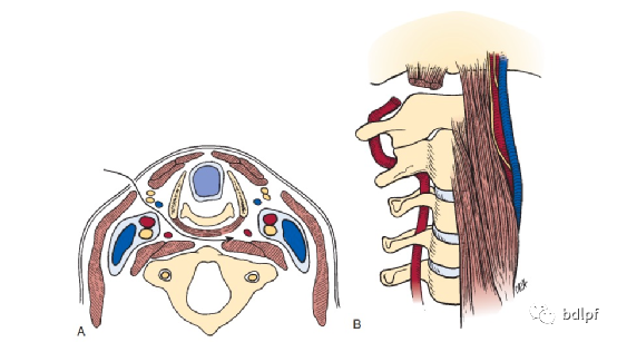
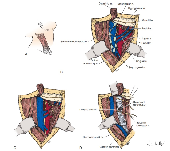
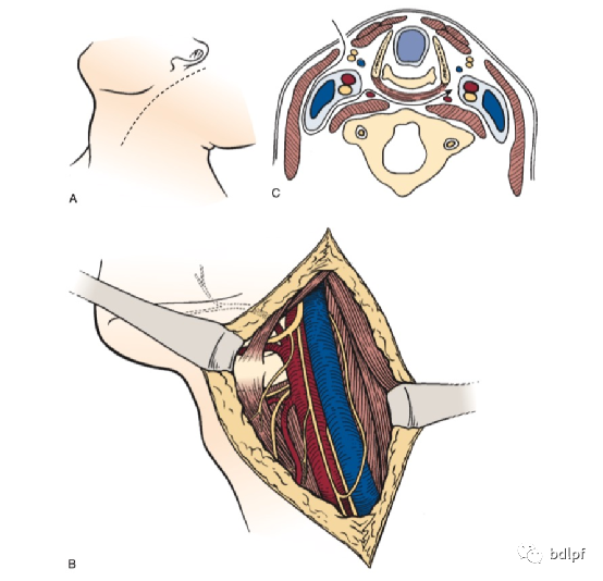
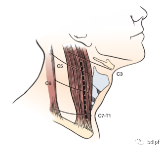
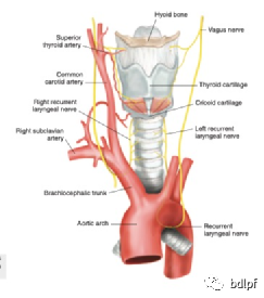
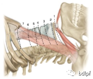
下颈椎安全距离为C3-6。C3椎体水平有喉上神经,C6椎体水平右侧有喉返神经。右利手医生可以右侧入路,但超过C6椎体水平建议左侧入路,避免损伤喉返神经。
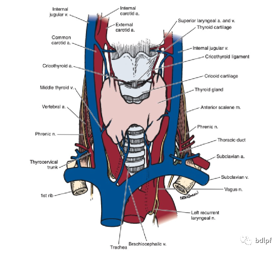
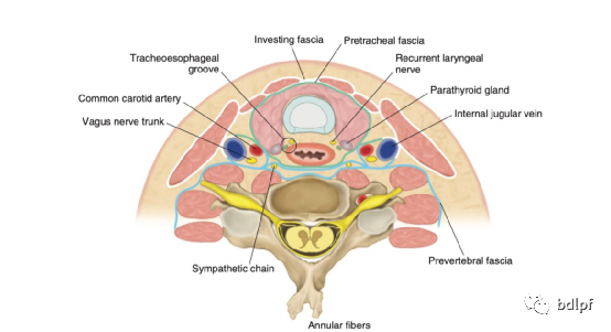
颈阔肌深面有颈前静脉和颈外静脉分支,注意止血。C3-6血管鞘与内脏鞘之间无重要血管,部分有喉中静脉可结扎。C3椎体水平有喉上动静脉,喉上神经,注意保护。
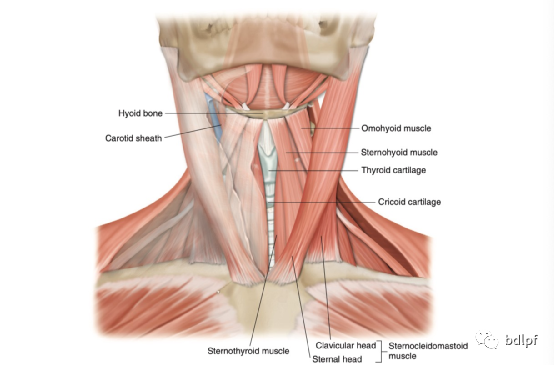
甲状舌骨肌在C5水平以上牵向内侧,以下牵向外侧。
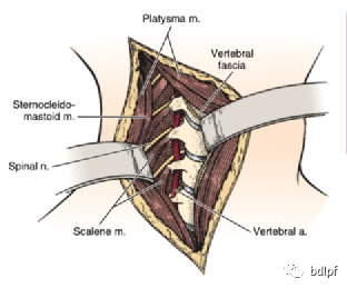
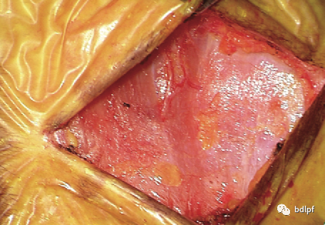
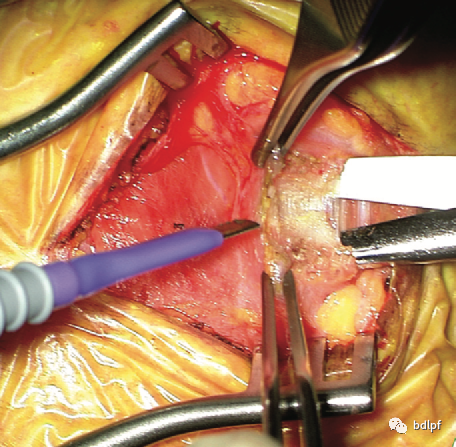
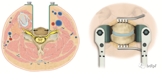
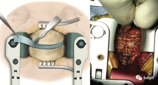
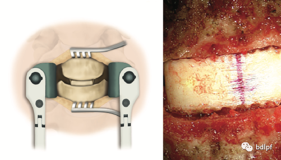
颈长肌表面有颈交感神经节,出血时尽量使用双击电凝,避免产生Horner综合征,应将椎前筋膜切开后骨膜下剥离,用自动拉钩向两侧牵开,保护食管。
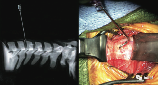
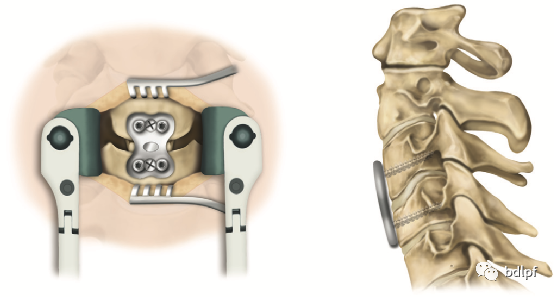
置入椎体钉后,透视时松开拉钩后颈长肌和食管回位,应用纱布隔离椎体钉,以免损伤食管。
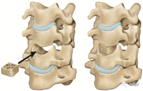
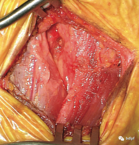
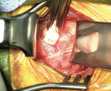
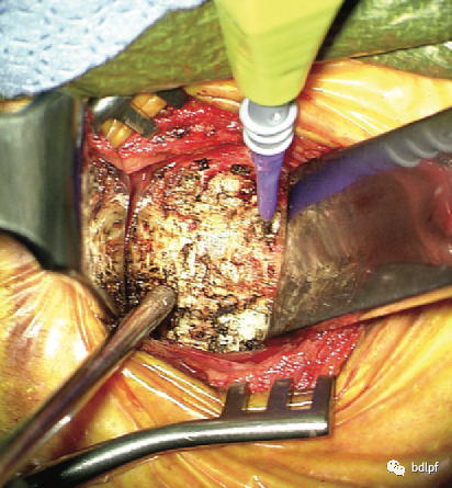
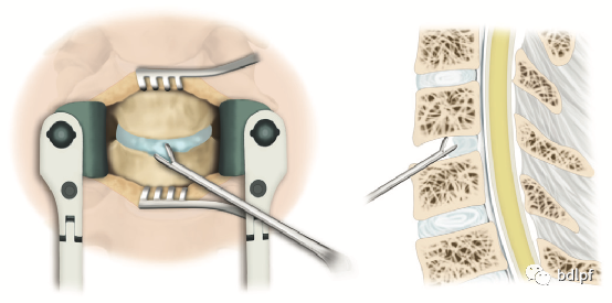
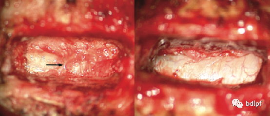
椎体后缘呈烧瓶样减压。骨赘较大时用动力魔钻打薄后可以用1mm枪钳咬除,或用刮匙刮除。在骨性减压前应保留后纵韧带,对脊髓的保护。
静脉丛位于两侧后纵韧带深层与中层内,向钩椎关节方向解压时容易损伤静脉丛血管,应最后减压,先进行无血管区解压,最后向两侧神经孔减压,当解压完毕,硬膜囊膨胀后出血停止。渗血可以用流体凝胶,脑棉等压迫止血,出血量较大时应用止血材料压迫3-5分钟可止血。
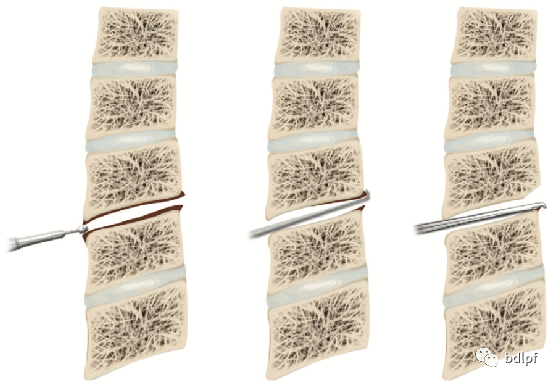
CACF术时最好行梯形减压,基底部宽度应等于脊髓横截面宽度,减压后脊髓能完全膨胀。
