
Minimally Invasive Posterior Lumbar Fusion Techniques
腰椎后路微创融合技术
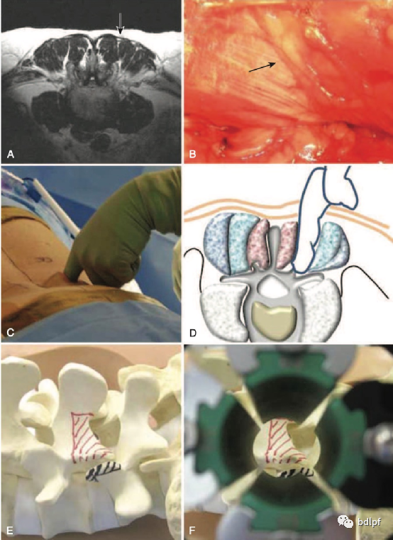
Minimally invasive spine transforaminal lumbar interbody fusion surgical corridor is shown. (A) Magnetic resonance cross-sectional image through the L4–L5 disc space showing the neurovascular plane between the multiidus and longissimus muscles (arrow). (B) Intraoperative photomicrograph showing the lateral aspect of the multiidus muscle and the neurovascular bundle (arrow). (C) Intraoperative image and (D) corresponding illustration showing the technique of manual blunt dissection to the surgical target site. (E) Image of a spine model with the surgical target site noted (red and black lines). (F) View of the surgical target site through a minimally invasive retractor.
微创脊柱经椎间孔腰椎椎间融合手术通道显示。(A)通过L4-L5椎间盘层面磁共振横截面图像,显示多裂肌和竖脊肌之间的神经血管平面(箭头)。(B)术中显微镜照片显示了多裂肌和神经血管束(箭头)的外侧面。(C)术中图像和(D)对应模拟图,显示出了手术目标部位的手法钝性分离解剖技术。(E)标明手术靶点的脊柱模型的图像(红线和黑线)。(F)通过微创牵开器观察手术靶点。
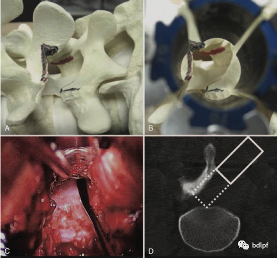
Minimally invasive spine transforaminal lumbar interbody fusion decompression is shown. (A) Image of a spine model with removal of the inferior articular process of the cephalad level and overhang of the superior articular process of the caudad level. (B) Corresponding view through a minimally invasive retractor. (C) Intraoperative photomicrograph of the dural tube with a Penield probe reaching to the contralateral side. (D) Postoperative computed tomographic scan with overlay of the surgical corridor.
微创脊柱经椎间孔腰椎椎间减压融合。(A)脊柱模型的图像,切除了上位椎体的下关节突和下位椎体的上关节突尖部。(B)微创牵开器下相应的视图。( C )术中椎管的显微照片,探针到达对侧。(D)术后计算机断层扫描,覆盖手术通道。
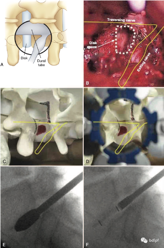
Minimally invasive spine transforaminal lumbar interbody fusion discectomy is shown. (A) Illustration and (B) corresponding photomicrograph of the surgical target site after facetectomy to expose the Kambin triangle, which is bounded medially by the dural tube, proximally by the exiting nerve root, and distally by the pedicle and superior endplate of the caudad vertebra. (C) Image of a spine model after facetectomy. The Kambin triangle is in red. (D) Corresponding view through a minimally invasive retractor. (E) Intraoperative image during discectomy showing a paddle distractor and sizer and (F) during cage insertion.
微创脊柱经椎间孔腰椎椎间融合椎间盘切除术。(A)插图和(B)关节突切除术后手术靶点的相应显微照片,以暴露Kambin三角形,该三角形内侧以硬膜囊为界,近端以走行神经根为界,远端由椎弓根和下位椎体上终板形成。(C)关节突关节切除术后脊柱模型的图像。Kambi三角形是红色的。(D)通过微创通道下相应的视图。(E)椎间盘切除术期间的术中图像显示试模大小和尺寸以及(F)融合器插入后的图像。
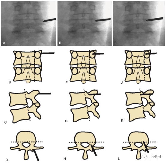
Percutaneous pedicle screw insertion requires scrupulous intraoperative imaging. (A, E, I) The trocar needle is inserted using a perfect en face anteroposterior image of the pedicle. The endplates should be lat and the top of the pedicle is in line with the superior endplate. The needle is inserted from a lateral to medial direction until the tip reaches the medial border of the pedicle (I and J). The C-arm is then brought under the table for a lateral view (B, F, J). If the needle is correctly inserted into the pedicle, the tip should be past the posterior vertebral body line (K and L). (A–D) Initial position of the needle in the anteroposterior, lateral, and axial planes, respectively. (E–H) Needle halfway across the pedicle. (I–L) Needle at the medial border of the pedicle. Once past the posterior vertebral body line, the needle can be inserted another 5 mm in preparation for insertion of the guidewire.
术中经皮椎弓根螺钉置入需要仔细进行影像学检查。(A, E, I)穿刺针在正位处于椎弓根的完美位置。上下终板应平齐,椎弓根顶部应与上终板平齐。针头从侧向向内侧插入,直到尖端到达椎弓根的内侧边缘(I和J)。然后将C型臂旋转到桌子下面进行横向视图(B,F,J)。如果针头正确插入椎弓根,尖端应超过椎体后线(K和L)。(A–D)针头的初始位置分别在矢状面、冠状面和轴位水平面的位置。(E–H)针头穿过椎弓根的一半。(I–L)针头在椎弓根内侧缘,一旦超过椎体后线,针头可以再插入5毫米,以准备插入导丝。
